
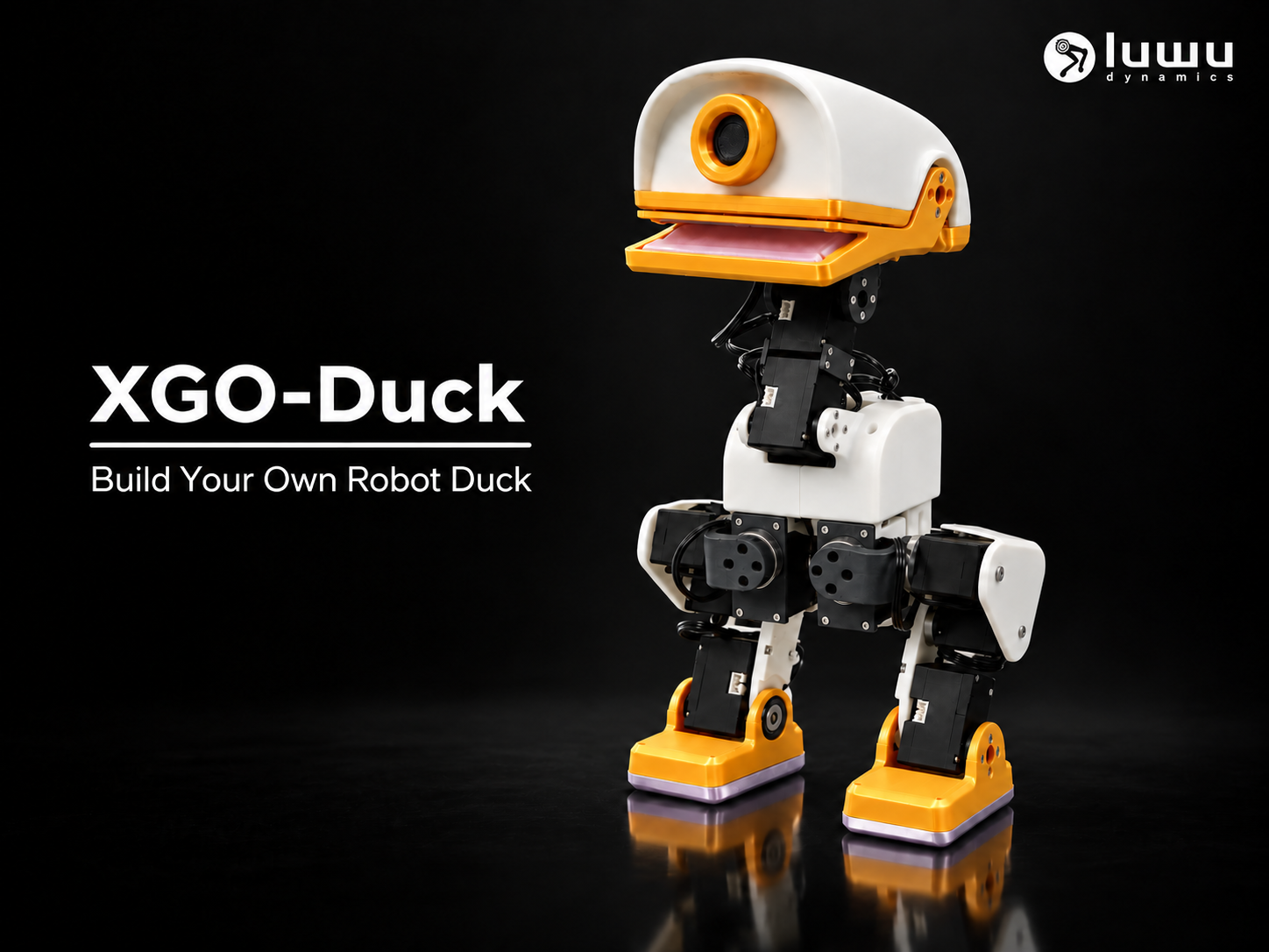
XGO-Duck — Build Your Own Robot Duck
Peso
328g
Tiempo
16h 32m
Precio
Cotiza este producto por WhatsApp
Contáctanos y te damos el precio según color y acabado
Las dimensiones dependen del diseño. Confirmamos las medidas exactas por WhatsApp.
Descripción
From printed parts to learned motion. Meet your next robotics project. XGO-Duck brings together a duck-shaped body, articulated legs, and a moving beak in a robot you can build and study. Print the structure, add the electronics, set up the servos, and explore how a learned policy becomes physical movement. Developed by Luwu Dynamics, XGO-Duck is based substantially on Microduck by Pollen Robotics, with adaptations for Arduino Uno Q, a custom expansion board, and Feetech 1910 serial servos. This is a 100% open-source DIY project. Printed parts alone do not make a working robot. Makers are expected to self-source all components using our provided Bill of Materials (BOM), fabricate the custom PCB, flash the firmware, and complete the joint calibration. Why build XGO-Duck? Give your prints a purpose: assemble the body, legs, neck, head and mouth into an actuated biped. Explore learned movement: the robot software includes walking, get-up and pick-motion policies. See how the system works: inspect the printable structure, electronics, firmware and training environment. Make it your project: experiment with appearance, document your build or investigate new policies. The Uno Q's Linux host runs the motion policy and browser interface. Its STM32 handles the servo bus and IMU. Together, they connect a software command to fifteen physical actuators. What can the robot do? FunctionAvailable in the current projectWalkingA learned walking policy controlled through the browser interfaceGetting back upA get-up policy and recovery state machinePick motionA pick policy with separate mouth controlSetup and calibrationBrowser pages for servo configuration and joint-zero calibrationFurther experimentsReinforcement-learning tasks and ONNX export toolsResults depend on the completed build, calibration, power supply and test conditions. No lifting capacity or all-terrain performance is specified. Additional simulation tasks are experiments, not a promise of extra ready-to-run robot modes. Before you print Recommended experience: multi-part printing, mechanical assembly, basic electronics and software setup. Read the assembly guide and purchasing list before starting. Match your printed parts, electronics and software to the same build revision. A changed shell, heavier part or different actuator can affect balance and motion. Materials and part quantities Rigid structure: body, leg and head components require the material and settings validated for the selected build revision. Flexible parts: the foot soles and mouth parts explicitly marked _tpu require TPU. Confirm the appropriate hardness and profile before printing. Repeated parts: filenames beginning with 2x_ indicate two copies. Check the plate layout before duplicating parts that may already be arranged twice. Left and right parts: keep the separate foot and shell files in their intended positions. Use the original model scale for the matching electronics and hardware. Check one bearing seat and one servo mount before printing the full set. After printing, clear supports from mating surfaces, bearing seats and cable passages without forcing the fit. Print-profile status The available local beta project saves an A1 / 0.4 mm nozzle / 0.20 mm layer-height configuration with PLA presets. These saved settings are a preparation reference; a complete tested printer/material compatibility list and TPU profile have not yet been established in the documentation. Check the specific print profile's material, orientation, supports and actual-print evidence before using it. Do not apply the rigid-part settings to the flexible parts. Print time and filament consumption depend on the final profile and are not quoted here. Hardware you will need ComponentQuantityKey specificationPurchasing Arduino Uno Q1Qualcomm QRB2210 Linux host + STM32U585 MCU; Arduino App environmentBuy LinkXGO-Duck expansion board1Drawing envelope 68.55 × 53.38 mm; QMI8658A IMU; servo/power interfacesBuy LinkFeetech 1910 serial servo15HD-1910-C001 ; 34 × 20 × 23 mm; 21 ± 2 g; 4–8.4 VBuy LinkServo cable(Default Servo Bundle)15Supplier reference: AMP2.0-3P, 3 positions, 2.0 mm pitch; PVC; 150 ± 5 mm/Battery pack and Charger118650 battery 8.4V; capacity >2,500 mAh; discharge rating >3C; XH2.54 connectorSelf-source based on specsM2 × 6 countersunk screws2002 mm nominal thread diameter × 6 mm length; countersunk headSelf-source based on specsM2.5 × 6 screws62.5 mm nominal thread diameter × 6 mm length; supplier specifies M2.5 × 6 for the servo output-shaft screwSelf-source based on specsM3 × 16 screws43 mm nominal thread diameter × 16 mm lengthSelf-source based on specsBearing, 10 × 15 × 3 mm210 mm bore × 15 mm outside diameter × 3 mm widthSelf-source based on specsBearing, 16 × 22 × 4 mm1116 mm bore × 22 mm outside diameter × 4 mm widthSelf-source based on specsServo specifications The supplied Feetech HD-1910-C001 specification lists 34 × 20 × 23 mm, 21 ± 2 g, a coreless motor, metal gears and a 12-bit magnetic encoder. The control interface is TTL half-duplex serial, with a 1 Mbit/s default bus rate. The maintainer confirms this is the project servo. Order this exact variant rather than an unspecified “1910” replacement. Supply voltage No-load speed Stall torque Stall current 4.8 V 0.137 s/60° 9 kgf·cm 1.2 A 6.0 V 0.109 s/60° 12 kgf·cm 1.6 A 7.4 V 0.088 s/60° 15 kgf·cm 2.0 A Supplier tolerance is ±10% for these figures. Working voltage is 4–8.4 V. Stall torque is not a continuous rating or a robot payload specification. The supplier cable specification is AMP2.0-3P, 150 ± 5 mm. Pins are 1: signal, 2: VCC, 3: GND in the supplier drawing's numbering. All wires may be black: verify the connector view and continuity rather than guessing polarity. The current XGO-Duck runtime addresses IDs 10–14, 20–24 and 30–34 at 1 Mbit/s. Configure one servo at a time before assembly. Power, hardware and budget notes The battery BOM additionally specifies capacity >2,500 mAh and discharge rating >3C. Screw quantities are purchasing quantities, not verified installed counts. Head/drive details and bearing shield/flange variants need checking against the actual build. Filament, adhesive, a compatible charger, a USB data cable and assembly tools also need to be accounted for; they are not separate entries in the source robot BOM. Estimated build cost is approximately US$400, not a kit price. The approximately one-hour battery-life target remains an estimate. From parts to first steps Check the build resources. Review the parts, BOM, assembly drawings and required electronics. Print and inspect. Verify fit and separate rigid parts from TPU parts. Prepare the controller. Set up the Uno Q runtime using its installation instructions. Configure the servos individually. Before assembly, connect one servo at a time, assign its ID and center it as documented. Assemble and route the cables. Follow the illustrated guide, paying attention to mirrored parts and connections that become enclosed. Calibrate the robot. Check all servo IDs and IMU feedback, then set joint zeros using the correct mechanical references. Test progressively. Begin with inference only, then a supported default pose, then small walking commands on a clear, level surface. Calibration and pose commands can move the servos. Keep fingers clear of joints and support the robot during setup; releasing torque can make it fall. Disconnect power before changing wiring. Build guides and software Hardware, printable parts and BOM Illustrated assembly guide Arduino Uno Q runtime and calibration Reinforcement-learning environment You do not need to train a model before using the bundled policies. A compatible, assembled and calibrated robot is still required. Questions before building Is it print-in-place? No. This is a multi-part assembly with servos, bearings, fasteners and electronics. Can I use a different printer? Check the individual profile and available build volume. Can I change the colors? Choose the appearance you like while keeping functional materials and fit appropriate. A color choice does not replace the need for TPU where specified. Can I replace the servos? Only after checking mechanical, electrical and control compatibility. Similar dimensions alone do not establish equivalent actuator behavior. Built on the work of others XGO-Duck draws extensively on Microduck and microduck_rl by Pollen Robotics. Luwu Dynamics' adaptation focuses on Uno Q integration, the expansion board, servo integration and the XGO-Duck simulation model. The training stack also builds on mjlab and BAM by Rhoban. Thank you to the upstream creators and contributors. XGO-Duck is maintained separately and does not claim their endorsement. Show us your duck Building one? Share a photo and tell us your printer, materials, hardware revision and what you learned. If something does not fit, include the exact part name and print settings so we can investigate. Your build report can make the next maker's first steps easier. Project and technical enquiries on Discord https://discord.com/invite/pfWrJeJRh6
Diseñador
CyberBionicMaker