
NextCore One
Peso
2829g
Tiempo
57h 17m
Precio
Cotiza este producto por WhatsApp
Contáctanos y te damos el precio según color y acabado
Las dimensiones dependen del diseño. Confirmamos las medidas exactas por WhatsApp.
Descripción
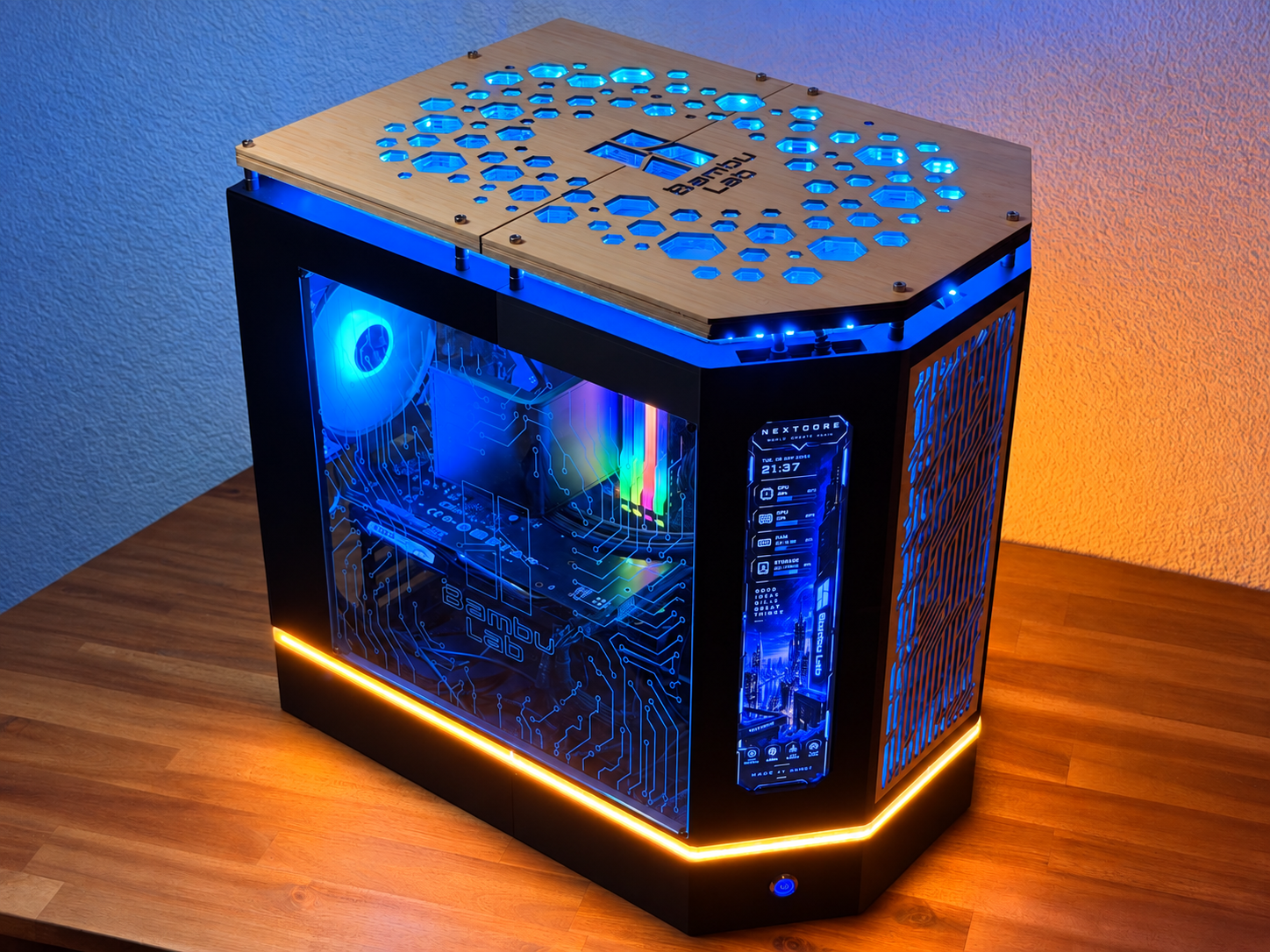
NextCore One – Build Your Own Custom PC Case Do you want to build your own PC, but not inside a standard off-the-shelf case? NextCore One combines 3D printing, acrylic, wood, lighting, and custom design options into a completely unique PC case. The main body consists of 13 individual 3D-printed parts that are assembled together. The combination of the black structure, wooden elements, acrylic panels, and integrated LED strips creates a very distinctive look. The acrylic panels can also be customized with laser engraving, just like on my own build shown in the pictures. With dimensions of approximately 433 × 306 × 413 mm (W × D × H), the NextCore One still offers plenty of space for different hardware configurations. Current features of the NextCore One: Supports Mini-ITX, Micro-ATX, and ATX motherboards Space for up to 3 × 120 mm fans Supports a 360 mm radiator with three fans, as used in my build, as well as smaller options such as 240 mm radiators Mounting options for 2 × SSDs and 2 × HDDs Integrated front display for temperatures, system information, animations, or other content Integrated LED strip around the lower section Additional LED lighting across the top and front Combination of 3D-printed parts, acrylic, and real wood Acrylic panels can be individually designed and laser engraved This is the first version of the NextCore One. If you would like to see specific changes, additional mounts, support for different hardware configurations, or other modifications, feel free to leave a comment. If several people are interested in the same feature, I can look into adding it as another version. Build it. Customize it. Make it your own. – NextCore One. Boost MeThank you NextCore One – Hardware & Parts List Below is the hardware and additional parts I used for my own NextCore One build. You do not have to use exactly the same PC hardware, but this configuration has been tested with the case. PC Hardware Motherboard: ASUS PRIME B450M-A – Micro-ATX CPU: AMD Ryzen 5 3400G Graphics Card: ASUS Dual GeForce RTX 3060 V2 OC Edition – 12 GB GDDR6 RAM: Corsair Vengeance RGB Pro – 16 GB DDR4-3200 (2 × 8 GB) Power Supply: be quiet! System Power 9 – 500 W, 80+ Bronze SSD: Apacer Panther AS350 – 256 GB SATA III HDD: WD Blue – 1 TB SATA III Cooling TRYX Panorama SE ARGB 360 Black 360 mm AIO liquid cooler 3 × 120 mm RGB fans Integrated 6.5" AMOLED display The NextCore One also supports other compatible 360 mm or smaller cooling solutions. Front Display AISHICHEN 11.26" Mini Monitor 1920 × 440 IPS display HDMI video input USB-C power Mini-HDMI to HDMI cable required The display works like a normal secondary monitor and can be used for temperatures, system information, animations, AIDA64 layouts, or other content. The AISHICHEN model uses HDMI for the picture and USB-C for power. Additional Electronics SinLoon 16 mm illuminated PC Power Button PWM Fan Splitter for connecting multiple fans EZDIY-FAB 12 V RGB to 5 V ARGB Converter, if required by your motherboard Required PSU, SATA, fan, RGB/ARGB, HDMI and USB cables Parts from Maker’s Supply All Maker’s Supply components used in my build are listed here and can also be added to the MakerWorld BOM. BT3×5 BHCS Self Tapping Screw (20PCS) – AA221 – 1 Pack Used for the front acrylic panel (4 screws) and graphics card mounting (1 screw). M3×4×25 SHSS Machine Screw (5PCS) – AA126 – 4 Packs Used for the three case fans (12 screws total) and the upper wooden assembly (8 screws). 20 screws required in total. M3×5×4 Round Threaded Brass Heat-Insert Nut (20PCS) – AB012 – 2 Packs Used for the fan mounts, graphics-card mounting points and other threaded mounting positions. Approximately 40 inserts are recommended. M3×14 SHCS Machine Screw (20PCS) – AA160 – 1 Pack Used mainly for the motherboard mounting system. Approximately 10–12 screws are required. 4×8×8 mm Oil Impregnated Bronze Bushings (20PCS) – ED004 – 1 Pack Used as spacers underneath the upper wooden panels. 16 bushings are required in total – two per mounting point. S-shape LED Strip Light (WS2812B RGB) – KA002 – 1 Pack Used for the upper illuminated section around the acrylic and wooden panels. The strip is approximately 5 m long, runs on 5 V and can bend sideways, making it ideal for following the shape of the case. Lower LED Lighting For the lower section of the case, I recommend using approximately 1.5 m of continuous COB RGB LED strip. A 1 m strip also works, but it leaves approximately 10 cm at the rear without illumination. With a 1.5 m strip, you can route the light completely around the case and simply cut off the excess. For my recommended setup: PAUTIX 5 V RGB COB LED Strip – 1.5 m Continuous COB lighting without visible individual LED dots Cuttable USB powered Used for the complete lower illuminated edge The 1.5 m PAUTIX version has a continuous COB design with 816 LEDs per meter. Other Materials Required CA glue / super glue 3D-printed NextCore One parts Laser-cut acrylic panels Laser-cut wooden panels Suitable fan cables / extensions if required Cable ties or other cable-management accessories Important: The exact PC hardware can be changed. The case is designed to support Mini-ITX, Micro-ATX and ATX motherboards, but dimensions of graphics cards, power supplies, radiators and other components can vary, so always check your hardware dimensions before assembly. NextCore One – Assembly Guide Before you start, make sure all printed parts are clean and that all support material has been removed. Especially check the connection points, holes, and slots so that no small pieces of support or excess material interfere with the assembly. Step 1 – Assemble the Bottom Section Start by assembling the complete bottom section of the case. The parts already include printed alignment connectors that help position everything correctly. Remove all remaining support material and make sure the mating surfaces sit completely flush. Once everything fits correctly, glue the parts together using CA glue / super glue. Step 2 – Install the Power Button Insert the power button into the opening at the front of the bottom section and secure it from the rear using the supplied nut. For now, simply place the cable inside the case. We will route and organize it properly later. Step 3 – Install the Lower LED Strip Now install the LED strip around the entire lower section of the case. I recommend using approximately 1.5 meters and trimming off the excess once you have completed the full loop. In my prototype I only used a 1-meter strip, which leaves around 10 cm at the rear without lighting. Since this area is at the back of the case, it is hardly noticeable, but 1.5 meters will give you a cleaner result. I used a continuous COB-style LED strip, which creates a much more uniform light without visible individual LEDs. The LED strip I used is included in the parts/material list. Step 4 – Test the Lower Lighting Before continuing, connect the LED strip and make sure that the entire strip works correctly. Also check that it sits evenly around the case and that there are no sharp bends or sections that have come loose. Step 5 – Assemble the Rear Sections Next, assemble the lower and upper rear sections. Just like with the bottom section, first test-fit the printed connectors, make sure everything sits flush, and then glue the parts together with super glue. Step 6 – Install the Rear Frame Make sure the left-side section for the graphics card is installed in the correct position. After that, attach the four rear frame elements to the bottom section. Once these parts are installed, the main structure of the case should already start to look like the finished frame. Step 7 – Install the Heat-Set Inserts Now install the heat-set threaded inserts into the prepared holes. There are mounting points for the graphics card on the left side and additional threaded inserts for the fan mounts on the right side. Carefully melt the inserts into the plastic using a soldering iron. Make sure they remain straight while being inserted and do not push them too deep into the printed parts. Step 8 – Install the PSU, SSDs and HDDs You can now install the power supply unit (PSU) as well as your SSDs and HDDs in the rear section. The current design provides mounting positions for: 2 × SSD 2 × HDD You can also begin routing the PSU cables through the large rear opening. The open rear section gives you plenty of room to work before the remaining panels are installed. Step 9 – Route the PSU Cables Route the required PSU cables through the prepared openings before installing the motherboard. Try to roughly separate the cables by where they will be needed later. This makes the final wiring much easier. Step 10 – Route the Mainboard Power Cables Guide the required cables through the openings in the case. The cables needed in the lower area can be routed through the lower opening. The 8-pin EPS/CPU power cable for the motherboard should be routed upward before the motherboard is installed. There is enough space provided for this cable at the top of the case. Step 11 – Prepare the Motherboard Mounts Insert a screw through each required motherboard mounting hole from the rear. Then screw the included 10 mm printed spacers/standoffs onto the screws. These spacers create the correct distance between the motherboard and the printed case structure. Step 12 – Check the Motherboard Standoffs At this point, all mounting screws should be installed and the printed spacers should sit on them. The spacers only need to hold lightly on the screws for now. Their main purpose at this stage is to stay in position so that the motherboard can easily be placed and screwed down in the next step. Step 13 – Install the Motherboard and Radiator Place the motherboard onto the prepared spacers and screw it into position. In my build, the water-cooling system was already connected to the motherboard, so I installed the motherboard and radiator together rather than removing everything again. The radiator can be screwed into the upper mounting area from above. It does not need to be supported across its entire surface—the provided mounting points are sufficient to hold it securely. Route the 8-pin CPU power cable past the rear-left side of the cooler. There is a small gap in this area that should provide enough space for the cable. Step 14 – Install the Graphics Card Insert your graphics card into the motherboard and check that everything lines up correctly. At this stage, I also routed the cable from the rear LED strip through one of the remaining openings where there was still enough space. Step 15 – Secure the Graphics Card The case includes several mounting holes for securing the graphics card. Choose the holes that match the position of your GPU and screw the card into place. Because graphics cards and motherboards can vary slightly in their dimensions and slot positions, please let me know in the comments if your particular hardware does not line up correctly. I currently only have my own motherboard and graphics card available for testing, so additional feedback is very helpful for improving compatibility. Step 16 – Install the Rear Fans and Finish the Internal Wiring Before installing the front section, mount the rear/right-side fans and connect them to the motherboard or your fan controller. This is also the best time to finish the main internal wiring. Connect your: motherboard power CPU power graphics card power SSDs HDDs fans power button lighting Make sure everything is connected before closing the front of the case, because access will become more limited afterwards. Step 17 – Assemble the Front Frame Now glue the individual parts of the front frame together. As before, test-fit everything first and only apply glue once you are sure that all sections are correctly aligned. Step 18 – Install and Glue the Front Frame to Complete the Case Now install the fully assembled front frame onto the main case. This step completes the entire 3D-printed structure of the NextCore One. Carefully position the front frame and slowly guide all of the printed connectors into their corresponding openings. You may need to insert the frame at a slight angle and gently move it up, down, or from side to side until everything slides into place. This part can be a little fiddly, so take your time and do not force anything. Make sure that all connectors are properly seated and that no cables are trapped between the parts. Once everything is correctly aligned and the front frame sits flush with the rest of the case, glue the connection points together using CA glue / super glue. After this step, all 3D-printed parts of the main case are assembled and the complete housing structure is finished. Step 19 – Install the Side Fan Now install the remaining fan in the prepared mounting position inside the case. First make sure that the required heat-set threaded inserts are already installed in the provided holes. Then position the fan and secure it with the appropriate screws. Finally, route the fan cable neatly toward the motherboard or fan controller and connect it. Step 20 – Test the Complete System Before continuing with the decorative panels and upper cover, power on the PC and test the complete system. Check that the PC starts normally and make sure all important components are working correctly. This includes the fans, water cooling, lower LED strip, power button, storage drives, and all other connected hardware. Also check that no cables are touching any of the fans and that everything inside the case looks correct. If something needs to be changed, now is the best time to do it before the remaining covers are installed. Step 21 – Install the Front Display Now slide the small display into the prepared opening at the front of the case. Route the display cable over the top toward the left side of the case. There is a dedicated opening on the left side that can be used to guide the cable into the interior. Step 22 – Route and Connect the Display Cable Guide the display cable through the opening on the left side. From there, route it downward through the inside of the case and then out through the large opening in the lower section. You can now connect the display cable to the motherboard or the corresponding controller/interface you are using. Step 23 – Start Installing the Upper LED Strip Now install the LED strip that will illuminate the upper section of the case. Connect the LED strip at the rear and begin attaching it along the left side. The LED strip I used for my build is also listed in the parts/material list. Step 24 – Route the LED Strip Toward the Front Guide the LED strip upward and through the same area where the cable for the small display was routed. Continue toward the front and attach the strip slightly away from the outer edge, as shown in the picture. Once you reach the right side, guide the LED strip through the small prepared opening. Step 25 – Route the LED Strip Around the Upper Section Continue routing the LED strip around the upper perimeter of the case. The acrylic and wooden panels will later sit in front of this area, allowing the light to shine through and create the illuminated effect around the top section. Keep the LED strip positioned as evenly as possible while working your way around the case. Step 26 – Route the LED Strip Back Toward the Rear Continue attaching the LED strip toward the rear of the case, following the path shown in the picture. Try to keep the strip straight and neatly positioned so that the lighting will look even once all covers are installed. The upper cover, acrylic panels, and wooden elements can now be prepared. Step 27 – Assemble the Upper Layer Structure Now install the lower plate of the upper section together with the two intermediate plates. Use the required M3 screws together with the included spacers. The spacers and screws required for this section are included in the parts list. Install all eight screws and tighten them properly so that the complete structure is held firmly and everything is correctly aligned. Step 28 – Route the LED Strip Through the Upper Assembly Now guide the LED strip through the rear opening and around the complete upper assembly. Continue all the way around and then route the strip back out through the rear opening again. There is not a lot of space in this area, so make sure the LED strip sits as flat and close to the printed case as possible. This is important because the acrylic and wooden panels will later sit directly above this area. Step 29 – Test the Upper LED Strip Before closing the upper section, test the LED strip again. Make sure the entire strip lights up correctly and check that the light is distributed evenly around the case. It is much easier to reposition the strip now than after the upper panels have been installed. Step 30 – Attach the Upper Acrylic Panels Now attach the inner acrylic panels to the upper cover. Carefully position the acrylic pieces and secure them using a few small drops of CA glue / super glue. You do not need to cover the entire surface with glue. A few small fixing points are enough. Make sure everything is correctly aligned before the glue sets. Step 31 – Attach the Front Acrylic Panel Repeat the same process with the acrylic panel for the front section. Place the acrylic panel into its intended position, carefully align it, and secure it using a few small drops of super glue. Allow the glue to set before continuing. Step 32 – Install the Upper Covers and Wooden Panels You can now install the complete upper cover assembly together with the wooden and acrylic elements. The easiest way is to work one side at a time. Slowly remove the screws from one side of the upper structure, place the cover and the corresponding panels into position, and then guide the screws back through the complete assembly. Tighten the screws again before moving to the other side. The parts may move slightly while the screws are removed, so take your time and keep everything aligned. Step 33 – Tighten the Complete Upper Assembly Once all covers, acrylic panels, and wooden elements are in position, carefully tighten all screws again. Do not tighten one screw completely while the others are still loose. It is better to tighten them gradually so that the complete upper assembly remains evenly aligned. Once everything is tightened, the upper section should feel solid and securely connected to the rest of the case. Step 34 – Final Check The NextCore One is now almost finished. Check the complete case one last time and make sure: all screws are tight all acrylic panels are seated correctly all wooden panels are aligned the LED strips are working the display is working all fans are running the water cooling is working no cables are touching moving parts Then power on the complete PC once again and enjoy the finished build. Your NextCore One is now fully assembled.
Tags
Diseñador
Dominik