
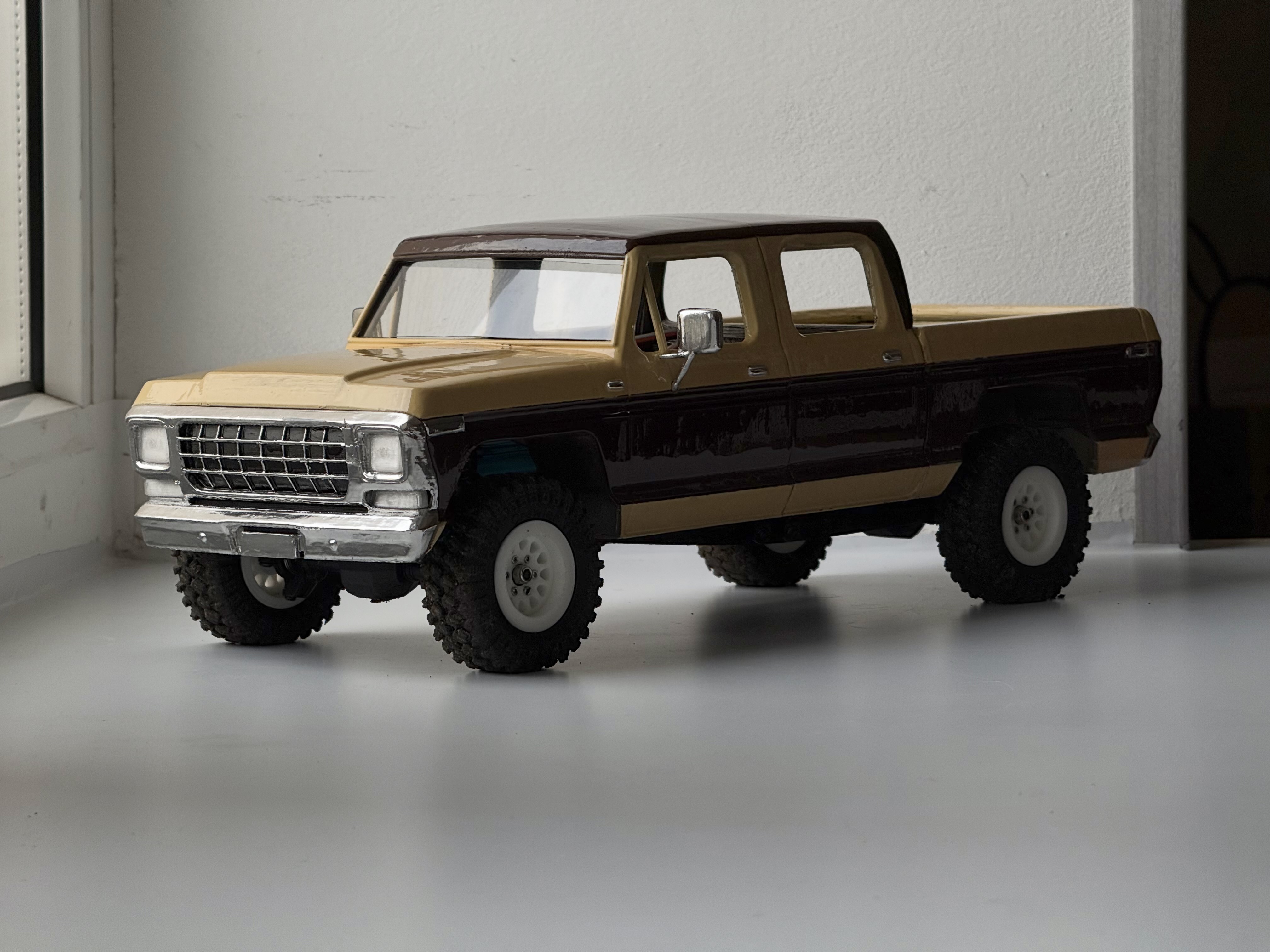
TRX4M F250 Super Cab Body
Peso
451g
Tiempo
32h 27m
Precio
Cotiza este producto por WhatsApp
Contáctanos y te damos el precio según color y acabado
Las dimensiones dependen del diseño. Confirmamos las medidas exactas por WhatsApp.
Descripción
This project consists of three main parts: A body based on the 1978 F250 Super Cab, with provisions for lighting (designed for 3 mm LEDs) Extended rear trailing arms for converting a standard TRX4M (NOT DESIGNED FOR THE HIGH TRAIL CHASSIS) into a long-wheelbase, large-scale pickup A rear driveshaft extender designed to withstand the required loads while still being easy to print My goal was to develop a conversion kit that would turn the standard TRX4M chassis into a long-wheelbase pickup. The base body was created using the Image to 3D Model tool in MakerLab. I then refined the raw model in Nomad Sculpt (surface cleanup and removal of unnecessary geometry) and Tinkercad (precise body-to-chassis mounting dimensions and suspension component design). All parts of this project went through multiple test prints (more than 1 kg of filament was used for prototypes in total) to achieve the simplest and most reliable printing process possible. For this reason, I strongly recommend not changing the orientation or placement of the parts on the build plate. All parts can be printed even on an A1 Mini. Body Assembly Connect the two cab halves using the square roof connector and the lower connectors. After gluing the two cab halves together, install the inner connector inside the cab to hide any visible light coming through a possible gap at the seam. To make sure you install it in the correct orientation, there are triangles on its underside indicating the direction toward the front of the body. This part is designed to provide the best possible fit and should be installed AFTER INSTALLING THE SQUARE ROOF CONNECTOR. Glue the tailgate to the main bed section. There are four holes in the rear of the cab and the front of the bed. They are designed for short pieces of filament (1–1.5 cm) to be glued into them. These filament pieces act as alignment pins for positioning the cab and bed. Glue the cab and bed together. At this stage, if you plan to install lighting, I recommend routing all the wires for the front and rear lights. For the rear light wiring, you may need to make holes in the front wall of the bed (which is also the rear wall of the cab). A soldering iron with a bent tip works well for melting these holes. I didn't include pre-made holes in the model because not everyone will need to install rear lights. Glue the headlight and turn signal lenses into the front bumper/grille (if you're installing lights, glue the LEDs in place at this stage as well). You can then glue the bumper to the cab. I recommend using rubberized double-sided adhesive tape, and then additionally securing it from the inside with a couple of drops of hot glue. Glue the rear light lenses into the tailgate (if you're installing lights, glue the LEDs in place at this stage as well). I recommend installing the side mirrors after painting the body. Chassis Conversion Remove the stock rear trailing arms. The shock towers only need to be replaced if you plan to install dual rear shocks. Based on my experience, I recommend using dual rear shocks because of the relatively high weight of the body, especially if you also plan to add accessories to the bed or tow a trailer (the trailer hitch and trailer itself are currently in development). If you already have upgraded/stiffer springs for your shocks, you can keep the stock shock tower. Install the extended trailing arms. Choose the appropriate version depending on whether you're using single or dual rear shocks. The trailing arms have separate left and right versions, which are labeled in the project. You can also identify them visually: the triangle should be on the outside and point toward the front of the chassis, while the shock mounting holes should be offset toward the top. The lower shock mounting point attaches to the outside of the trailing arms. The trailing arms attach to the axle at the same mounting points where the shocks are mounted in the stock setup. Use one of the pivot balls as a spacer here. Driveshaft Extender The extender consists of several parts. After printing, make sure the bottom surfaces that were in contact with the supports are smooth enough. Clamp the cross-shaped shaft between the two halves. The grooves must line up. If the connection isn't perfectly tight or there is some play, don't worry—the assembly will be additionally secured by the outer sleeve. The outer sleeve is printed using the spiral vase method to provide strength against the internal pressure generated during operation. Slide this tube over the previously assembled shaft. No glue is required here—the parts are designed to move relative to each other. Install the driveshaft extender between the two ends of the stock driveshaft. This is easiest to do with all the links installed except for one of the lower links. After installing the extender, attach the remaining link and tighten everything into place. Important Questions & Answers “The model has visible polygons on the surfaces.” Yes, the model has some imperfections on the surface because the base 3D model was generated from photos using an AI tool. However, I manually corrected many of the artifacts from the AI generation using Nomad Sculpt. The surface imperfections are easily hidden after sanding and painting the body. “The driveshaft extender won't be able to handle the load.” It has survived real-world testing involving steep climbs, hard acceleration, and all kinds of challenging obstacles (including some situations that a scale build like this really shouldn't be subjected to). I can guarantee its reliability and durability for trail driving. And in the unlikely event of a failure, it is very easy to replace. “Why not just make a longer chassis?” My goal was specifically to create a conversion kit for the stock chassis. Combined with the clipless body, it allows you to convert a regular stock TRX4M into this long-wheelbase pickup in just 30–40 minutes. “Will there be a version for the High Trail?” In theory, I could make one, but since I don't have a stock High Trail chassis on hand, I can't guarantee that I'll be able to get the dimensions of the extended frame exactly right. I prefer to publish projects that I'm confident in and have personally tested on my own setups. Future Plans for This Project Interior — there will be a half-interior version, extending below the window line to provide more realistic depth. Trailer hitch and trailer — already in development
Tags
Diseñador
Gravelboi