
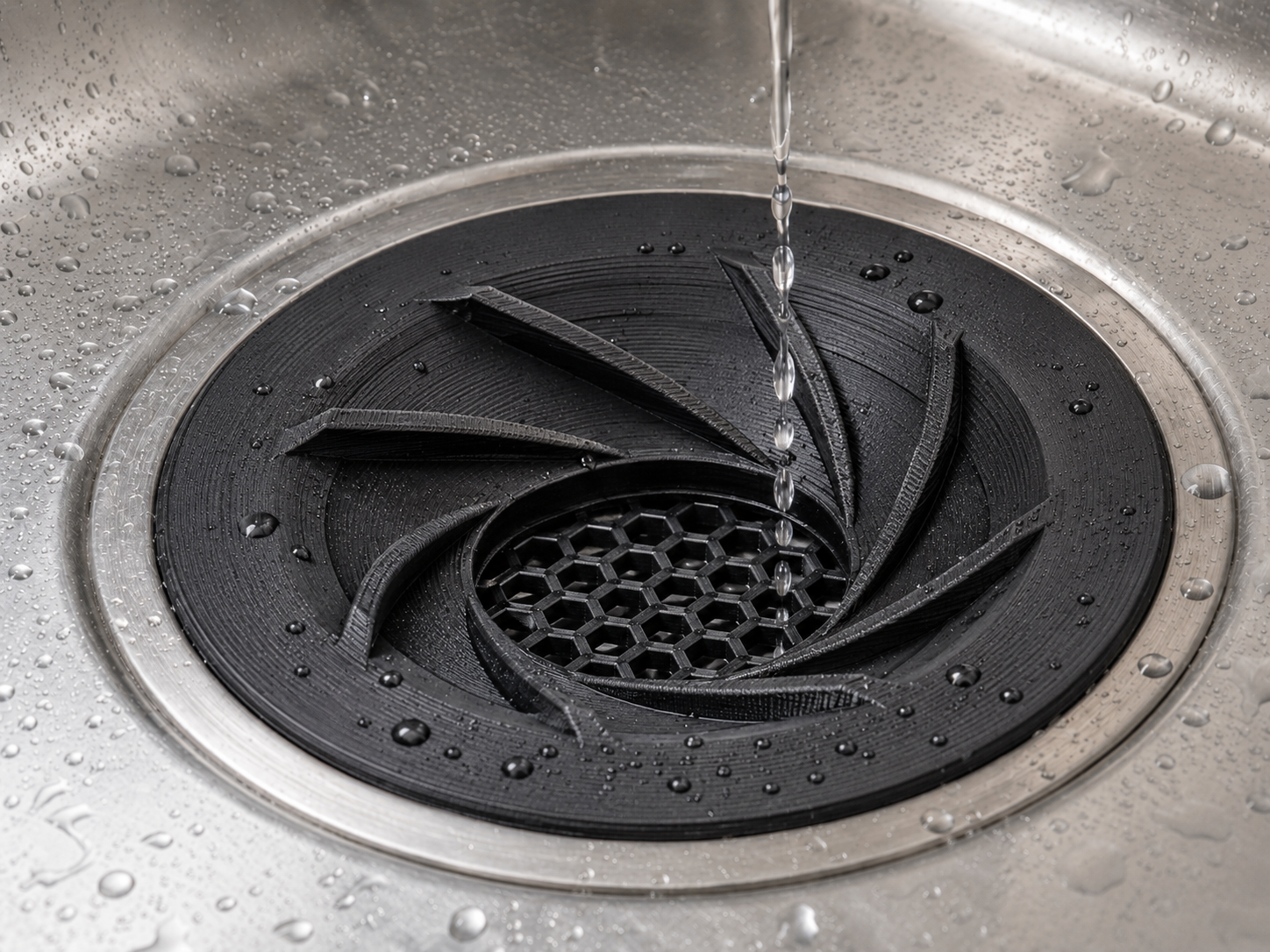
Customizable Swirl Sink Filter
Peso
44g
Tiempo
2h 40m
Precio
Cotiza este producto por WhatsApp
Contáctanos y te damos el precio según color y acabado
Las dimensiones dependen del diseño. Confirmamos las medidas exactas por WhatsApp.
Descripción
Parametric Swirl Sink Drain Filter + Removable Debris Catcher A fully customizable, two-part sink drain filter designed to guide water and debris toward the center while collecting larger particles before they enter the plumbing. The model contains both printable parts in one OpenSCAD file: Upper vortex plate — a wide seating flange, shaped funnel, and automatically generated spiral ribs. Lower removable catcher — a tapered cup with a honeycomb floor, optional center lift pin, and optional clearance for a centered drain screw or bolt head. The model can be generated from only the measured drain dimensions, or every relevant diameter, height, chamfer, wall, rib, hole, clearance, and surface-quality setting can be adjusted manually. All dimensions are in millimetres. Main Features Automatic sizing from the measured upper drain diameter, lower drain diameter, and usable depth Support for cylindrical, tapered, and reverse-tapered drain openings Local fit checking at the actual depth of each inserted component Adjustable radial and bottom clearances Optional centered screw or bolt-head clearance with an automatically generated closed hood Automatically generated spiral ribs that adapt to the active funnel dimensions Configurable rib count, spacing, direction, sweep, curvature, width, height, taper, and root fillets Optional central lift pin with configurable stem, grip sphere, and rounded root reinforcement Configurable honeycomb floor Automatically dimensioned annular locating seat between the two parts Adjustable entry chamfer and fit clearance for the locating seat Multiple geometry-resolution presets plus full custom control Separate, assembled, exploded, and print-layout output modes Optional transparent drain reference for visual fit checking Built-in validation for geometrically impossible combinations Quick Start For most drains, only the controls in 01 - Output need to be changed. Measure the clear internal diameter at the top of the drain. Measure the clear internal diameter at the bottom of the usable space. Measure the usable vertical depth. Enter those values in drain_upper_d, drain_lower_d, and drain_usable_depth. Leave auto_size_from_drain = true. Enable drain_center_screw_enabled only when a screw, bolt head, or similar centered obstruction rises from the drain bottom. Select output_part = "assembly" and enable show_reference_sink to inspect the fit. Return to output_part = "print_layout" for the printable arrangement. Use resolution_preset = "fine" for a high-quality final export. A first test print is recommended whenever the drain is difficult to measure, visibly irregular, or heavily tapered. How to Measure the Drain 1. Upper Diameter Measure the smallest clear internal diameter at the upper seating plane, directly below the surface on which the wide printed flange will rest. Enter this measurement as drain_upper_d. Do not measure the outside diameter of the visible metal ring. Measure only the clear opening available to the printed body. 2. Lower Diameter Measure the clear internal diameter at the bottom of the selected usable depth. Enter this measurement as drain_lower_d. For a cylindrical drain, use the same value for drain_upper_d and drain_lower_d. For a drain that narrows downward, enter a smaller lower diameter. For a drain that widens downward, enter a larger lower diameter. The automatic system assumes a straight wall between the two measured diameters. 3. Usable Depth Measure vertically from the upper seating plane to the drain bottom or to the first obstruction that blocks the full cross-section. Enter this measurement as drain_usable_depth. A small centered screw does not need to be treated as the end of the usable depth. It can be described separately with the centered-screw options. 4. Center Screw or Bolt Head When a centered screw, bolt head, or similar obstruction rises from the drain bottom, measure: the maximum outside diameter of its widest point; its height above the drain bottom. Enter these measurements as drain_center_screw_d and drain_center_screw_h. The current obstruction model assumes a centered, vertical feature rising from the bottom. Crossbars, off-center screws, and complex mechanisms require conservative measurements or manual sizing. How Automatic Drain Sizing Works When auto_size_from_drain = true, the drain is represented as a straight conical frustum defined by: drain_upper_d; drain_lower_d; drain_usable_depth. The program does not simply scale the complete object uniformly. It calculates the available diameter independently at four critical depths: top of the upper inserted body; bottom of the upper inserted body; top of the lower catcher; bottom of the lower catcher. The main body diameters are scaled from the reference proportions and then limited so that they remain inside the measured drain envelope after applying drain_radial_clearance. The upper-body and catcher heights are scaled so that the assembled insertion depth fits inside: drain_usable_depth - drain_bottom_clearance The selected locating-seat insertion depth is included in this calculation, so overlapping the two parts does not incorrectly increase the final depth. The following dimensions generally follow the automatic radial or vertical scale: upper inserted body diameters; catcher top and bottom diameters; upper body and catcher heights; upper flange diameter; throat and funnel diameters; funnel elevations; honeycomb area diameter; nominal lift-pin height; spiral-rib geometry. Small functional dimensions remain absolute so they do not become unprintably thin: wall thickness; bottom thickness; chamfers; raised lips; honeycomb hole size and web thickness; connector clearance and seat depth; pin diameter and sphere diameter; root-fillet radii. The detailed dimensions in later sections are therefore not completely ignored in automatic mode. They act as the base proportions from which the fitted model is derived. The automatic upper flange preserves at least approximately 8 mm of radial seating surface beyond the upper inserted body. Because the drain measurements do not describe nearby sink walls or curved surfaces, always verify that the generated flange diameter fits the available flat area. Automatically Dimensioned Connection Between the Parts The connection is a removable annular locating seat, not a snap-fit and not a watertight seal. The existing upper rim of the catcher enters a shallow groove in the underside of the vortex plate. No extra locking tab is required. When connector_mode = "seat", the groove width is calculated automatically from the real catcher geometry across the selected connector_seat_depth. The calculation includes: catcher upper-lip diameter; lip top chamfer; lip overhang; catcher wall thickness; tapered inner wall; inner top chamfer; selected insertion depth; connector_radial_clearance on both the inner and outer sides. This means the groove automatically updates when the catcher dimensions, wall, lip, chamfers, automatic drain size, or seat depth are changed. There is no separate groove-width parameter to maintain manually. connector_entry_chamfer adds a 45-degree lead-in at the groove opening. The model automatically reduces the requested chamfer when there is not enough material near the outer body, central throat, groove width, or seat depth. The seat centers the catcher, reduces lateral movement, and helps the pin remain aligned with the upper opening. It is intentionally removable and should not require force to assemble. Complete Customizer Guide 01 - Output auto_size_from_drain Enables or disables automatic drain-based sizing. true: the main dimensions are derived from the measured drain profile. false: the detailed dimensions in the following sections are used directly. Use automatic mode for normal customization. Use manual mode for unusual geometries or when exact independent control is required. drain_upper_d Clear internal diameter at the upper seating plane. This defines the available opening immediately below the printed flange. drain_lower_d Clear internal diameter at the bottom of drain_usable_depth. The model assumes a straight taper between the upper and lower values. drain_usable_depth Usable vertical distance below the seating plane, measured to the drain bottom or first full-width obstruction. drain_radial_clearance Clearance left between the drain wall and each inserted part, measured per side. A value of 0.50 mm reduces the usable diameter by 1.00 mm in total. Suggested starting points: 0.25–0.35 mm for accurate measurements and a calibrated printer; 0.50 mm for a normal removable fit; 0.70–1.00 mm for rough surfaces, uncertain measurements, or easier removal. drain_bottom_clearance Vertical space left between the catcher bottom and the measured drain bottom. Increase it when the drain bottom is uneven, the depth measurement is uncertain, or additional free space is required. drain_center_screw_enabled Enables accommodation for a centered screw, bolt head, or similar obstruction rising from the drain bottom. When the obstruction would intersect the catcher floor, the model automatically creates a lower recess and a closed tapered hood above it. If the obstruction is already below the available bottom gap, no unnecessary hood is generated. drain_center_screw_d Maximum outside diameter of the screw or bolt head. Measure its widest point, not only the threaded shaft. drain_center_screw_h Height of the centered obstruction above the measured drain bottom. drain_center_screw_radial_clearance Additional radial clearance around the screw or bolt head. Increase it when the obstruction is not perfectly round, is slightly off-center, or was difficult to measure. drain_center_screw_vertical_clearance Additional space retained above the screw or bolt head. This prevents the closed hood from touching the obstruction. output_part Selects the geometry shown and exported: print_layout: both printable parts placed separately on the build plane; assembly: the two parts shown in their assembled position; exploded: the two parts separated vertically; top: upper vortex plate only; basket: lower catcher only. Use assembly and exploded for inspection. Use print_layout, top, or basket for printable exports. exploded_gap Vertical separation between the two parts in exploded view. It does not alter either printable part. print_spacing Horizontal spacing between the two objects in print layout. Increase it when using a wide brim or when the slicer requires more clearance between separate objects. assembly_clearance_z Additional vertical offset between the two parts in assembly and exploded previews. This is a visualization and diagnostic control. Positive values show a gap; negative values show additional overlap. It does not change the individual part geometry. show_reference_sink Displays the sink reference, measured drain envelope, and optional center screw in assembly or exploded view. Recommended fit-check setup: output_part = "assembly" show_reference_sink = true 02 - Resolution resolution_preset Controls circular smoothness and spiral-rib sampling. draft: fast preview and small files; standard: balanced quality and render time; fine: recommended for most final FDM exports; ultra: very smooth geometry and larger files; custom: enables the manual resolution controls below. custom_preview_facets Number of circular facets used during OpenSCAD F5 preview when custom quality is selected. Higher values improve roundness but make interactive previews slower. custom_render_facets Number of circular facets used during F6 rendering or MakerWorld generation when custom quality is selected. This affects cylinders, tapered bodies, chamfers, fillets, and the grip sphere. custom_rib_step_mm Approximate sampling distance along each spiral rib when custom quality is selected. Lower values create smoother ribs but increase polygon count and rendering time. Typical values: 1.0–1.5 mm for fast tests; 0.5–0.8 mm for normal final models; 0.2–0.4 mm for very high detail. rib_samples_override Forces an exact number of longitudinal sections along every rib. Set it to 0 for automatic sampling. Manual values are intended for advanced testing; unnecessarily high values can create very large meshes. 03 - Upper Plate Dimensions In automatic mode, the main diameters and body height act as base proportions and are adapted to the drain. Flange and lip thicknesses remain absolute. upper_outer_d Maximum outside diameter of the wide upper seating flange. In automatic mode, it is scaled from the base value while preserving at least approximately 8 mm of radial seating surface beyond the upper inserted body. upper_body_bottom_d Outside diameter at the lower edge of the upper inserted body. In manual mode this is the exact diameter. In automatic mode it is scaled and limited by the drain diameter available at its depth. upper_body_top_d Outside diameter at the upper shoulder immediately below the flange. This is normally the largest inserted diameter of the upper part. upper_body_h Height of the tapered upper body below the flange. In automatic mode, this height is scaled together with the catcher height to fit the measured usable depth. upper_flange_h Thickness of the main upper flange, excluding the small raised outside lip. Increase it for greater stiffness. Excessive values increase material use and raise the top surface. upper_outer_lip_h Height of the small raised lip around the outside edge of the flange. Set it to 0 to remove the raised height. upper_outer_lip_w Radial width of the raised outside lip. 04 - Upper Plate Chamfers Each chamfer has two independent dimensions: _h: vertical height; _w: radial width. Set either dimension to 0 when that chamfer is not required. upper_bottom_chamfer_h Vertical height of the chamfer at the lower outside edge of the upper body. upper_bottom_chamfer_w Radial width of the lower outside body chamfer. It also affects the material available around the automatically sized connector seat. upper_shoulder_chamfer_h Vertical height of the transition between the tapered body and upper shoulder. upper_shoulder_chamfer_w Radial width of the body-to-shoulder transition. upper_flange_lower_chamfer_h Vertical height of the chamfer below the large seating flange. upper_flange_lower_chamfer_w Radial width of the chamfer below the large seating flange. upper_flange_top_chamfer_h Vertical height of the chamfer on the top outside edge of the main flange. upper_flange_top_chamfer_w Radial width of the top outside flange chamfer. upper_lip_inner_chamfer_h Vertical height of the chamfer on the inner edge of the raised outside lip. upper_lip_inner_chamfer_w Radial width of the inner raised-lip chamfer. upper_lip_outer_chamfer_h Vertical height of the chamfer on the outer edge of the raised outside lip. upper_lip_outer_chamfer_w Radial width of the outer raised-lip chamfer. 05 - Funnel and Throat The funnel profile is defined by a central opening, a flat annular land, an intermediate knee, and an outer joining point. For valid geometry, the diameters must increase outward and the funnel elevations must rise from the center toward the outside. throat_d Diameter of the central straight opening through the upper plate. A larger opening allows larger debris and higher flow but leaves less funnel surface. A smaller opening retains more upper surface but may clog more easily. The grip sphere must remain smaller than the generated throat diameter so the catcher can pass through the upper plate. throat_bottom_chamfer_h Vertical height of the chamfer at the underside of the central opening. throat_bottom_chamfer_w Radial width of the underside throat chamfer. throat_top_chamfer_h Vertical height of the transition between the straight opening and the funnel floor. throat_top_chamfer_w Radial width of the upper throat transition. funnel_floor_z Height of the lowest flat funnel surface above the underside of the upper plate. Lower values create a deeper funnel, provided enough material remains for the throat chamfers and connector seat. funnel_floor_land_d Outside diameter of the flat annular area surrounding the central opening. A larger value creates a wider flat ring. Excessive values reduce the sloped area available to guide debris inward. funnel_knee_d Diameter of the intermediate break point in the funnel profile. funnel_knee_z Height of the intermediate break point. Together with funnel_knee_d, it controls how the funnel slope is distributed. funnel_outer_d Diameter at which the sloped funnel joins the outer flange area. It must remain smaller than the upper flange diameter. funnel_outer_drop Vertical distance between the top of the main flange and the outer edge of the funnel. A larger value lowers the outer funnel edge. A smaller value moves it closer to the flange top surface. 06 - Optional Center Opening Rim throat_lip_enabled Adds or removes a raised rim around the central opening. The default is false because a raised rim can retain debris and interrupt the smooth path toward the catcher. throat_lip_h Height of the optional raised rim. It has no effect while throat_lip_enabled = false. throat_lip_w Radial width of the optional raised rim. throat_lip_outer_chamfer Chamfer size on the upper outside edge of the optional rim. 07 - Spiral Ribs The spiral ribs are regenerated from the active throat and funnel geometry rather than uniformly scaled as fixed objects. rib_count_override Forces an exact number of ribs. Set it to 0 for automatic calculation from the active circumference and rib_target_pitch. rib_target_pitch Target circumferential spacing used to determine the automatic rib count. Lower values create more ribs. Higher values create fewer ribs. It is ignored when rib_count_override is greater than 0. rib_clockwise Selects the swirl direction when viewed from above. Toggle it to reverse the complete pattern. The preferred direction is a design choice and is not determined by geographic hemisphere. rib_phase_deg Rotates the complete rib pattern around the center without changing the rib shape. Use it to alter visual alignment or position the gaps relative to nearby sink features. rib_sweep_override Forces the angular sweep of every rib in degrees. Set it to 0 for automatic calculation. Larger values create longer and more strongly curved ribs. rib_curve_power Controls how curvature is distributed along each rib. Around 1: relatively even curvature; above 1: more curvature concentrated toward the outer region; below 1: more curvature concentrated toward the center. rib_inner_gap Radial clearance between the rib starts and the flat throat land. Increase it to move the rib tips farther from the central opening. rib_outer_gap Radial clearance between the rib ends and the outer edge of the funnel. Increase it to shorten the ribs at the outside. rib_width_inner_override Forces the rib width at the inner end. Set it to 0 for automatic sizing. rib_width_outer_override Forces the rib width at the outer end. Set it to 0 for automatic sizing. Different inner and outer widths create a tapered rib. rib_height_inner_override Forces rib height near the central opening. Set it to 0 for automatic sizing. rib_height_outer_override Forces rib height near the outer funnel edge. Set it to 0 for automatic sizing. rib_top_clearance Minimum vertical clearance between the rib tops and the top plane of the main flange. This prevents automatically generated ribs from exceeding the intended upper profile. rib_root_overlap Amount by which each rib penetrates into the funnel surface. This hidden overlap ensures a reliable solid union and avoids merely coplanar contact. Small positive values are recommended. rib_root_fillet_r Radius of the rounded reinforcement where both sides of each rib meet the funnel. Set it to 0 to disable the fillets. Suggested FDM values: 0.40–0.50 mm for a subtle reinforcement; 0.50–0.80 mm for normal use; 1.00 mm for the strongest available root. The default 0.60 mm is a balanced value for a 0.4 mm nozzle. rib_inner_taper_fraction Fraction of the rib length used to taper the inner tip. For example, 0.10 tapers approximately the first 10% of the rib. rib_outer_taper_fraction Fraction of the rib length used to taper the outer tip. For example, 0.16 tapers approximately the final 16% of the rib. rib_tip_factor Minimum width and height retained at the two rib tips. Lower values create sharper tips. Higher values create thicker and stronger tips. 08 - Lower Catcher Dimensions In automatic mode, the main catcher diameters and height are adapted to the measured drain. Wall, floor, lip, and chamfer dimensions remain absolute. basket_top_d Maximum outside diameter of the catcher upper lip. In automatic mode, it is limited by the local drain diameter and by the radial space required for the locating seat beneath the upper body. basket_bottom_d Outside diameter at the bottom of the catcher. This controls the catcher taper and is limited by the measured drain diameter at the deepest insertion point. basket_h Overall catcher height, excluding the lift pin and grip sphere. In automatic mode, it is scaled together with the upper body height. basket_wall Nominal catcher wall thickness. For a 0.4 mm nozzle, approximately 1.2–1.6 mm is a practical starting range. Increasing it improves stiffness but reduces internal volume and available honeycomb area. basket_bottom_t Thickness of the perforated honeycomb floor. A thicker floor improves rigidity and strengthens the pin or screw hood, but reduces internal depth. basket_lip_h Vertical height of the upper retaining and locating lip. The selected connector_seat_depth should not consume the solid floor or invalid parts of the catcher geometry. basket_lip_overhang Radial projection of the upper lip beyond the tapered catcher body. A larger overhang creates a more pronounced locating edge and changes the automatically generated seat geometry. 09 - Lower Catcher Chamfers Each chamfer uses independent vertical height and radial width controls. basket_bottom_chamfer_h Vertical height of the chamfer at the lower outside edge of the catcher. basket_bottom_chamfer_w Radial width of the lower outside catcher chamfer. basket_lip_lower_chamfer_h Vertical height of the transition below the upper catcher lip. basket_lip_lower_chamfer_w Radial width of the transition below the upper lip. basket_lip_top_chamfer_h Vertical height of the top outside chamfer on the catcher lip. This chamfer is included when the connector groove calculates the real outer envelope of the inserted lip. basket_lip_top_chamfer_w Radial width of the top outside lip chamfer. basket_inner_top_chamfer_h Vertical height of the chamfer at the inside top edge of the catcher. This feature helps debris enter the cup and is included when the connector groove calculates the inner lip envelope across the selected insertion depth. basket_inner_top_chamfer_w Radial width of the inside top catcher chamfer. 10 - Honeycomb Bottom honeycomb_area_d Diameter of the circular area occupied by the hexagonal openings. In automatic mode, it is scaled and also limited by the actual catcher bottom diameter and wall thickness. hex_hole_flat Flat-to-flat size of each hexagonal opening. Larger holes increase open area and allow larger particles to pass. Smaller holes retain finer debris but can clog more quickly. hex_web Minimum material width between adjacent hexagonal openings. Larger values create a stronger floor. Smaller values increase the open flow area. For a 0.4 mm nozzle, values near 1.2–1.6 mm are a practical starting range. hex_rotation Rotates the complete honeycomb pattern. A hexagonal pattern repeats every 60 degrees, so this setting mainly changes alignment and appearance. honeycomb_edge_margin Additional solid margin retained around the outside of the honeycomb area. The model also reserves a central solid island automatically when the lift pin or centered-screw hood requires support. 11 - Center Lift Pin center_pin_enabled Adds a central grip pin to the catcher so the cup can be lifted together with the collected debris. center_pin_d Diameter of the straight pin stem. A larger stem is stronger but occupies more of the central honeycomb area. center_pin_h Height of the straight stem above the inside catcher floor, excluding the grip sphere. In automatic mode, the height is adjusted to keep the grip at approximately the same protrusion above the upper plate when the drain depth changes. When a centered-screw hood is generated, the pin is mounted on top of that hood and shortened automatically so the sphere remains at approximately the intended elevation. center_pin_ball_d Diameter of the spherical grip at the top of the pin. A larger sphere is easier to hold, but it must: be at least as large as center_pin_d; remain smaller than the generated throat_d. If the sphere cannot pass through the upper opening, the model stops with a validation error. center_pin_root_fillet_r Radius of the rounded reinforcement where the pin meets the catcher floor or centered-screw hood. Set it to 0 to disable the fillet. For a 5 mm stem: 0.50–0.70 mm creates a compact reinforcement; 0.70–1.00 mm provides greater resistance to bending. The default 0.80 mm is a strong general-purpose value. The central honeycomb exclusion area expands automatically to support the reinforced base. 12 - Connection Between Parts connector_mode Selects the connection style: seat: automatically dimensioned annular locating seat; none: flat underside without a locating groove. The seat centers the catcher but does not lock it and is not intended to create a watertight seal. connector_radial_clearance Radial clearance applied on both the outer and inner sides of the catcher material entering the seat. Suggested FDM starting points: 0.15–0.20 mm for a close fit on a well-calibrated printer; 0.25–0.35 mm for a normal removable fit; 0.40–0.60 mm for a loose fit, rough material, or uncertain calibration. Because this value is radial, the corresponding diametral difference is twice the entered value. connector_seat_depth Depth by which the catcher upper lip enters the underside of the upper plate. The groove width is generated automatically from the actual outer lip and inner wall profile across this depth. Increasing the depth may include a wider portion of a tapered wall and therefore can change the groove width automatically. A deeper seat improves guidance but requires sufficient material below the funnel and above the catcher floor. connector_entry_chamfer Requested size of the 45-degree lead-in chamfer at the seat entrance. The effective chamfer is automatically reduced when necessary to preserve: the outer underside wall; clearance from the central throat; adequate groove width; the selected seat depth. Set it to 0 for a sharp groove entrance. 13 - Optional Sink Reference These controls affect only the transparent reference shown when show_reference_sink = true. They do not alter the printable parts. reference_sink_hole_d Diameter of the simplified sink opening used in manual sizing mode. When automatic sizing is enabled, the displayed opening uses drain_upper_d instead. reference_sink_t Thickness of the simplified sink sheet and drain-envelope wall shown in the preview. reference_sink_ring_d Outside diameter of the simplified reference ring. In automatic mode it acts as a base value and may be scaled or enlarged so the ring remains visible around the generated flange. In manual mode it is used directly. Recommended Starting Settings For a normal FDM print with accurate drain measurements: auto_size_from_drain = true drain_radial_clearance = 0.50 drain_bottom_clearance = 0.50 resolution_preset = "fine" throat_lip_enabled = false rib_root_fillet_r = 0.60 center_pin_enabled = true center_pin_root_fillet_r = 0.80 connector_mode = "seat" connector_radial_clearance = 0.25 connector_seat_depth = 0.80 connector_entry_chamfer = 0.30 output_part = "print_layout" For a first fit test, use draft or standard resolution and print only the necessary component when possible. Printing Recommendations The parts are designed to print in the orientation generated by print_layout. Suggested starting settings: 0.4 mm nozzle 0.16–0.24 mm layer height 3–4 wall loops at least 4 top and bottom layers 15–30% infill PETG or another material suitable for the expected water temperature and cleaning products The upper vortex plate and main catcher geometry normally do not require supports in their generated orientation. The optional grip sphere can require limited support depending on the sphere diameter, stem diameter, layer height, and printer overhang performance. Inspect the sliced preview and use a small painted or organic support only beneath the lower part of the sphere when necessary. PLA is suitable for prototypes and fit tests, but select the final material according to the actual sink temperature, detergents, mechanical handling, and cleaning method. A printed part is not automatically food-contact certified simply because the base filament is marketed for food-related use. For best strength around the lift pin: keep the rounded pin-root fillet enabled; use sufficient walls; avoid pulling the pin sharply sideways; inspect layer adhesion before regular use. Assembly and Use Print the upper vortex plate and lower catcher. Remove stringing and check that every honeycomb opening is clear. Insert the catcher lip into the annular locating seat beneath the upper plate. Confirm that the connection is centered and removable without excessive force. Place the assembly into the drain. Water and debris are directed toward the central opening by the funnel and spiral ribs. Larger particles remain in the lower catcher. Lift the catcher with the center pin, empty it, rinse both parts, and reinstall them. The locating seat is intended for alignment only. It should not be glued unless a permanently joined assembly is specifically required. Fit Troubleshooting The Complete Assembly Is Too Tight in the Drain Increase drain_radial_clearance, verify that the smallest real drain diameter was measured, and check for hidden steps or deposits inside the drain. The Assembly Sits Too Deep or Touches the Bottom Increase drain_bottom_clearance or reduce drain_usable_depth to the true available value. The Catcher Is Too Tight in the Upper Locating Seat Increase connector_radial_clearance in small steps, for example by 0.05 mm. The Catcher Moves Too Freely Reduce connector_radial_clearance, provided the printer is dimensionally consistent. The Catcher Does Not Enter the Seat Easily Increase connector_entry_chamfer, reduce connector_seat_depth, or check the printed lip for elephant foot and over-extrusion. The model automatically limits the chamfer if surrounding material is insufficient. The Connector Groove Appears Wider After Changing the Catcher This is expected. The groove is automatically recalculated from the actual catcher lip, inner tapered wall, chamfers, clearance, and insertion depth. The Center Screw Still Interferes Verify the widest screw-head diameter and height, then increase drain_center_screw_radial_clearance or drain_center_screw_vertical_clearance. The Grip Sphere Cannot Pass Through the Upper Plate Reduce center_pin_ball_d or increase the base throat_d. The model intentionally rejects impossible combinations. The Model Renders Slowly Use draft or standard, increase custom_rib_step_mm, reduce custom_render_facets, or leave rib_samples_override = 0. Important Limitations The automatic drain model assumes a straight linear taper between the upper and lower measured diameters. It accurately represents: cylindrical openings; regular conical openings; openings that widen toward the bottom. It does not fully represent: stepped internal walls; multiple changes in taper; side protrusions; crossbars; off-center screws; drain mechanisms with moving parts; non-circular openings. For an irregular drain, use the most restrictive measurements, increase the clearances, reduce the usable depth to the first obstruction, or disable automatic sizing and configure the detailed dimensions manually. The automatic measurements also do not define the amount of flat sink surface available around the drain. Verify that upper_outer_d does not contact nearby walls, curves, seams, or accessories. This model is a removable debris filter, not a plumbing seal, valve, structural drain component, or substitute for required plumbing hardware. Validation and Error Messages The OpenSCAD model uses validation checks to stop generation when a combination cannot produce valid geometry. An error may appear when, for example: the drain is too small after applying radial clearance; the usable depth is too small after applying bottom clearance; the selected drain taper leaves no valid catcher taper; the honeycomb no longer fits inside the catcher; chamfers consume the available wall or height; the connector seat reaches the central throat or outer underside wall; the seat depth reaches the catcher floor; the center screw is taller than the measured drain depth; the screw hood cannot fit inside the catcher; the grip sphere is smaller than the stem or larger than the throat; the ribs have no valid radial or vertical space. When generation stops, read the console message and reduce the conflicting feature, increase the available drain dimensions, increase a relevant clearance, or restore the affected parameter to its default value. Reference Geometry and Design Notes The original principal dimensions: 112 mm upper flange diameter 88.01 mm lower diameter of the upper body 9.5 mm upper body height 11.5 mm upper overall height 85 mm catcher upper diameter 65 mm catcher lower diameter 12 mm catcher height With the default automatic drain measurements of: 94 mm upper drain diameter; 83 mm lower drain diameter; 21.2 mm usable depth; and the default clearances, the generated model reproduces the principal dimensions of the original reference geometry: 112 mm upper flange; 93 mm upper body diameter at the top; 88.01 mm upper body diameter at the bottom; 85 mm catcher upper diameter; 65 mm catcher lower diameter; 20.7 mm total insertion depth; 0.5 mm bottom clearance. The spiral ribs are regenerated from the active geometry, and the annular connector groove is regenerated from the actual catcher-lip envelope. Both systems therefore remain responsive when the overall model is resized or its detailed proportions are changed.
Tags
Diseñador
ilmanu