
Gear Lab – Parametric Gear Generator
Peso
3g
Tiempo
17m
Precio
Cotiza este producto por WhatsApp
Contáctanos y te damos el precio según color y acabado
Las dimensiones dependen del diseño. Confirmamos las medidas exactas por WhatsApp.
Descripción
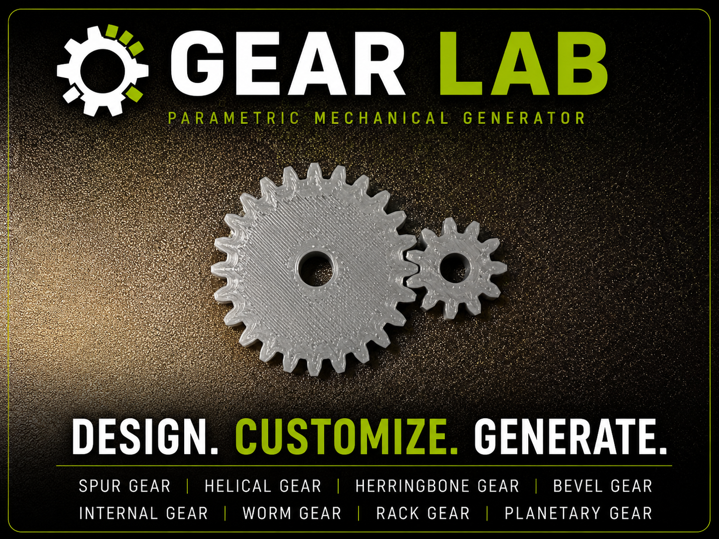
Gear Lab — Universal Parametric Gear Generator Gear Lab is a customizable mechanical gear generator designed for MakerWorld’s Parametric Model Maker and OpenSCAD. It lets you create everything from a simple spur gear to complete rack-and-pinion, planetary, bevel, and worm gear systems without having to manually model the tooth geometry. The idea is simple: choose what you want to make, enter the dimensions you care about, and generate the part. You do not need to understand every advanced gear parameter to use Gear Lab. Most common parts can be created using only the Quick Build section. The additional sections are there when you need more control. Boost MeIf this was helpful, then feel free to boost!What Gear Lab can generate Gear Lab currently supports: Standard gears Spur gears Helical gears Herringbone gears Gear sets Spur gear pairs Helical gear pairs Herringbone gear pairs Stacked (compound) gears with independently configurable upper and lower gears Rack systems Rack only Rack + matching gear Internal gears Internal ring gears Herringbone ring gears Planetary systems Sun gear Multiple planet gears Internal ring gear Assembled or separated layout Bevel gears Standard bevel gears Herringbone bevel gears Worm drives Worm screw Worm + matching worm gear set Gear Lab also includes customization features such as keyways, lightening holes, face recesses, countersinks, and rack mounting holes. Quick Start For most projects, begin with the Quick Build section. 1. Choose a Part Type Open Quick Build → Part Type and choose what you want Gear Lab to create. For example: Spur Gear creates one standard straight-tooth gear. Gear Pair creates two matching gears and automatically places them at the proper center distance. Rack Only creates a straight gear rack. Rack + Matching Gear creates both the rack and a compatible pinion gear. Planetary Gear creates a complete planetary arrangement. Worm Gear Set creates the worm and its mating gear. You can switch between these at any time and regenerate the model. Sizing Your Gear Gear Lab gives you two different ways to control gear size. Outside Diameter This is the easiest option for most users. Choose: Sizing Method → Outside Diameter Then enter approximately how large you want the finished gear to be. For example: Outside Diameter = 50 mm Gear Lab automatically calculates the required module from the selected tooth count. This is useful when you know: “I need this gear to be roughly 50 mm wide.” rather than knowing the exact gear module. Module Choose: Sizing Method → Module when designing gears that must mesh with an existing gear, rack, or mechanical system. Both mating components should use the same module and generally the same pressure angle. Common examples might be: Module 0.8 for smaller mechanisms Module 1 Module 1.5 Module 2 for larger printed mechanisms Larger modules produce larger and stronger teeth. Tooth Count Teeth control the number of teeth around the main gear. Increasing the tooth count produces a larger gear when the module remains constant. For mating gears, tooth counts also determine the gear ratio. For example: 20-tooth driving gear + 40-tooth driven gear gives approximately a 2:1 ratio. Gear Lab handles the actual tooth geometry automatically. Width Width controls the thickness of the gear along its axis. A thicker gear generally provides: more tooth engagement greater strength better durability but also uses more material. For lightweight prototypes, smaller widths may be sufficient. For power transmission, wider gears are usually preferable. Center Bore Bore controls the center shaft hole. For example: Bore = 5 mm creates a nominal 5 mm center opening. Set: Bore = 0 if you want the gear generated without a center hole. Motion & Tooth Style The Motion & Tooth Style section controls the actual orientation of the gear teeth. Pressure Angle The default is: 20° which is a very common general-purpose gear pressure angle. Other available options include: 14.5° 20° 25° 30° Unless you specifically need another value, 20° is a good starting point. Mating gears should use the same pressure angle. Helix Angle Used with: Helical gears Herringbone gears Helical gear pairs Herringbone ring gears Increasing the helix angle causes the teeth to become increasingly angled rather than straight. Helix Direction Choose: Right Left For compatible helical gear pairs, Gear Lab can automatically use opposite helix directions. Gear Pair Helper When Gear Pair is selected, the Gear Pair Helper controls the second gear. Pair Style Choose: Spur Helical Herringbone Both gears are generated using compatible geometry. Second Gear Teeth Controls the tooth count of the mating gear. Changing this allows you to create different gear ratios without manually calculating gear diameter. Second Gear Bore Controls the shaft opening for the second gear independently from the main gear. Pair Extra Spacing Adds a small amount of extra center distance between the two gears. The default: 0.15 mm provides a little additional freedom for 3D-printed parts. Increase this slightly if your printer produces gear pairs that mesh too tightly. Opposite Helix For helical gear pairs, enabling this automatically gives the mating gear the opposite helix direction. That helps ensure proper external gear meshing. Shaft and Keyway Options Gear Lab can generate either a simple round bore or a keyed shaft connection. Shaft Style Choose: Round for a normal circular center hole. Choose: Keyway to add a rectangular key slot to the bore. A keyway is useful when the gear must transmit torque through a keyed shaft rather than relying only on friction. Key Width Controls the width of the key slot. Key Depth Controls how far the keyway extends outward from the center bore. Key Angle Rotates the position of the keyway around the gear. For example: 0° 90° 180° 270° can be used to orient the key slot where needed. Lightweight Gear Options Large gears often contain unnecessary solid material in the center. Gear Lab can automatically create lightening holes to reduce: filament use print time rotating mass without changing the gear teeth themselves. Enable Lightening Holes Turn on: Lightening Holes to create a circular pattern of holes through the gear body. Hole Count Controls how many holes are placed around the gear. For example: 4 6 8 Hole Diameter Controls the size of each opening. Orbit Diameter Controls how far away from the gear center the holes are positioned. A larger orbit diameter moves the holes closer to the outer edge of the gear. Pattern Angle Rotates the entire lightening-hole pattern. This can help align holes with: spokes keyways mounting features cosmetic designs When using lightening holes, make sure enough solid material remains around the bore and beneath the gear teeth. Face Recesses Gear Lab can also remove material from the face of a gear instead of cutting completely through it. This creates a recessed or dished gear face. You can independently enable: Top Face Recess Bottom Face Recess Recess Diameter Controls the diameter of the recessed area. Recess Depth Controls how deeply the pocket cuts into the gear. This is useful for: reducing weight reducing filament creating clearance for nearby components creating a more mechanical or machined appearance The top recess cuts downward from the top face. The bottom recess cuts upward from the bottom face. You can use either side individually or both together. Bore Countersink The center bore can also include an inward countersink. Enable: Bore Countersink to create a tapered entry around the center hole. Countersink Diameter Controls the diameter of the opening at the surface. Countersink Depth Controls how far the taper extends into the gear. This can be useful for: easier shaft insertion chamfered bore edges countersunk fasteners eliminating sharp printed edges Rack Generator Gear Lab includes a dedicated parametric rack generator. Select: Rack Only to generate only the rack. Select: Rack + Matching Gear to automatically generate a compatible pinion beside the rack. Rack Length Controls the total length of the rack. Rack Height Controls the amount of solid body underneath the teeth. A taller rack generally gives you more material for mounting holes and greater stiffness. Rack Gear Teeth When using Rack + Matching Gear, this controls the tooth count of the pinion. The rack and gear automatically use compatible tooth geometry. Rack Gear Bore Controls the center hole of the matching pinion. Auto Mesh When enabled, Gear Lab automatically positions the pinion relative to the rack. Rack Mesh Clearance Adds a small amount of separation between the rack and gear. This is especially useful for FDM printing because printed parts rarely match their theoretical dimensions perfectly. Rack Mounting Holes Racks can include built-in mounting holes so they can be screwed directly to: frames 3D-printed assemblies wood aluminum extrusion accessories robotics projects moving mechanisms Enable: Rack Mounting Holes to turn this feature on. Screw Size Presets Choose: M2 M2.5 M3 M4 M5 M6 Gear Lab automatically selects a practical clearance-hole diameter for the selected screw. It then adds additional 3D-printing clearance. For example, the M3 preset starts with approximately a 3.2 mm clearance hole. With the default: Print Clearance = +0.20 mm the generated hole becomes approximately: 3.40 mm This gives an FDM printer some room for dimensional error. Hole Count Choose how many mounting holes should appear across the rack. Gear Lab automatically spaces them evenly. End Margin Controls the distance between the rack ends and the first/last mounting holes. You do not need to manually calculate each mounting-hole position. Print Clearance Adds additional diameter to every mounting hole. If your printer tends to produce undersized holes, increase this value slightly. A good starting value is: 0.20 mm The best value depends on: printer calibration filament layer height nozzle size Mounting Head Style Choose between: Straight A simple through-hole. Countersink Creates a tapered recess so a countersunk screw can sit closer to flush with the surface. Counterbore Creates a flat-bottom recess for screw heads such as socket-head screws. Head Depth Controls how deeply the countersink or counterbore enters the rack. Head Extra Diameter Adds additional room around the screw head. This is useful for FDM printing and slightly oversized hardware. Internal Ring Gears Select: Internal Ring to generate a gear with teeth facing inward. These are commonly used in: planetary gear systems compact reductions robotics mechanical transmissions Ring Wall Controls the amount of solid material surrounding the internal teeth. Increasing this value produces a stronger outer ring. Herringbone Ring Gear The Herringbone Ring option combines internal teeth with herringbone geometry. Herringbone teeth reverse direction at the center of the gear face. This can provide smoother engagement while visually creating a distinctive double-helical pattern. Planetary Gear Generator Select: Planetary Gear to create a planetary system. The generator automatically creates: one sun gear multiple planet gears an internal ring gear Sun Teeth Controls the number of teeth on the center gear. Planet Teeth Controls the teeth on each planet. The internal ring tooth count is derived from the sun and planet geometry so the components remain compatible. Planet Count Controls how many planet gears are included. Available values range from small arrangements to larger multi-planet systems. Assembled When enabled, the parts are shown in their assembled relationship. This is useful for: visualization checking geometry demonstrating the system Depending on how you intend to print the parts, you may want to separate them in your slicer afterward. Bevel Gears Select: Bevel Gear to create gears intended to transfer rotation between intersecting shafts. Bevel gears are useful for mechanisms where the direction of rotation must change. Bevel Angle Controls the partial cone angle of the gear. Bevel Tooth Width Controls the width of the teeth along the bevel surface. Gear Lab also includes: Bevel Herringbone for a herringbone-style bevel gear. Worm Generator Select: Worm to create the screw-like worm component by itself. Worm Starts Controls how many helical thread starts the worm uses. For example: 1 start 2 starts 3 starts 4 starts Increasing the number of starts changes how much the mating worm gear advances per worm revolution. Worm Length Controls the overall length of the worm. Worm Lead Angle Controls the angle of the helical thread. Worm Gear Set Select: Worm Gear Set to generate both: worm screw mating worm gear The system uses the same module, pressure angle, starts, and lead-angle settings so the components are created as a matching set. Worm Gear Teeth Controls the number of teeth on the worm wheel. Assembled When enabled, the worm and gear are positioned together for visualization. This makes it easier to see how the finished mechanism is intended to work. Render Quality The Quality setting controls how much geometric detail OpenSCAD uses. Choose: Draft for quick previews. Normal for routine editing. High for good final previews. Ultra for maximum smoothness. Higher quality can increase generation time significantly, especially for: planetary systems worm gears herringbone gears high tooth-count models For designing, I recommend Normal or High. Switch to Ultra only when you need the final geometry. A Simple Workflow You can create most parts with this process: 1. Choose the Part Type. For example, Spur Gear. 2. Choose your sizing method. Use Outside Diameter if you simply know how large the gear should be. Use Module if the gear must match another mechanical component. 3. Set Teeth, Width, and Bore. Those are the three most important dimensions. 4. Generate the model. Check that the overall proportions are what you expected. 5. Add optional features. Only open the sections you need: Keyway Lightening holes Recesses Countersink Rack mounting holes Gear pair options 6. Generate again. Inspect clearances before printing. 7. Print a small test when fit matters. For mating gears, shafts, keyways, and screw holes, printer calibration can affect the final dimensions. Tips for Successful 3D-Printed Gears For your first version of a mechanism, avoid making every clearance extremely tight. FDM prints have dimensional variation, particularly around small holes and gear tooth surfaces. A small amount of additional clearance can dramatically improve motion. For mating systems, always keep these compatible: Module Both components must use the same tooth size. Pressure Angle Mating gears should use the same pressure angle. Helical Direction External helical mating gears generally need compatible/opposite hand geometry. Gear Lab handles many of these relationships automatically when using its paired generators. For heavily loaded parts, also consider increasing: module gear width rack body height ring wall thickness rather than simply increasing infill. Designed for beginners, useful for advanced projects You can use Gear Lab as a very simple generator by touching only: Part Type → Size → Teeth → Width → Bore → Generate Everything else is optional. As your project becomes more advanced, the same file can also create keyed shafts, lightweight gears, recessed faces, mounted racks, gear pairs, planetary systems, bevel mechanisms, and worm drives without rebuilding the model from scratch. That is the main purpose of Gear Lab: one customizable file for a wide range of 3D-printable mechanical gearing projects.
Tags
Diseñador
CRUST