
Parametric PCB Mounting Tray Generator - OpenSCAD
Peso
12g
Tiempo
27m
Precio
Cotiza este producto por WhatsApp
Contáctanos y te damos el precio según color y acabado
Las dimensiones dependen del diseño. Confirmamos las medidas exactas por WhatsApp.
Descripción
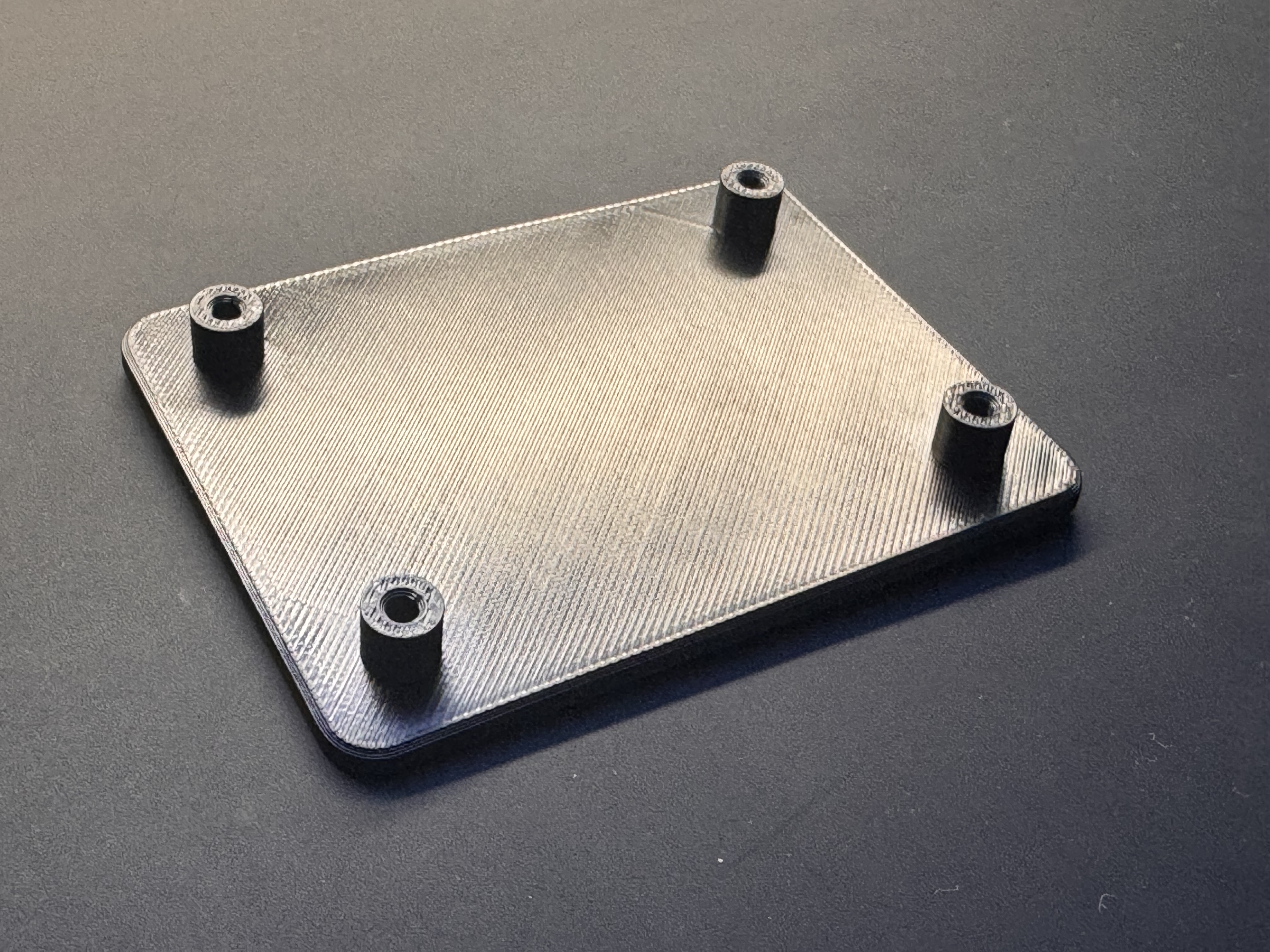
Boost MeThank You :)Parametric PCB Mounting Tray Generator Create fully customizable mounting trays for PCBs and electronics modules directly in MakerWorld’s Parametric Model Maker. The generator supports different PCB sizes, mounting-hole patterns, support heights, tray styles and retention methods. It is designed for electronics enclosures, control panels, test equipment, workshop projects, prototypes and custom installations. Custom PCB dimensions The tray can be adjusted to match the required board size. Available PCB settings include: PCB width PCB height PCB thickness edge clearance support height tray border corner radius The model is centered and generated with a flat underside for easy printing. Three PCB mounting styles Screw Standoffs Creates cylindrical supports for PCBs with mounting holes. The standoff system includes adjustable: outer diameter screw-hole diameter support height optional locating collar locating clearance screw-hole lead-in chamfer The locating collar can enter the PCB mounting hole and help position the board accurately before installation. Snap Clips Creates flexible side clips for boards without mounting holes. Clip width, thickness, overhang, clearance and the number of clips per side can be adjusted. The PCB rests on integrated supports and is retained by the clips without additional screws. Sliding Rails Creates two side rails with grooves for inserting the PCB from one end. Rail height, wall thickness, groove depth and groove clearance can be customized. One end is lowered to provide an insertion opening, while the opposite end can act as a stop. This style is useful when the PCB should remain removable without accessing mounting screws. Rectangular or individual mounting-hole layouts The screw-standoff version supports two different hole-layout modes. Rectangular Pattern Creates a regular two-hole or four-hole arrangement using horizontal and vertical spacing values. This is suitable for boards with symmetrical corner mounting holes. Individual Positions Up to eight mounting holes can be positioned independently. Each hole receives its own X and Y coordinate measured from the PCB center. This makes it possible to reproduce asymmetric or irregular mounting patterns found on many real circuit boards. The complete hole layout can also be rotated around the PCB center. Solid Tray or Open Frame Solid Tray Creates a continuous protective base below the PCB. This version provides maximum stiffness and separates the PCB from the mounting surface. Open Frame Creates a lightweight frame with internal support beams. Every active screw standoff is automatically connected to the nearest frame edge, including individually positioned mounting holes. This prevents unsupported standoffs and keeps the structure printable and stable. External mounting options The tray can be attached to an enclosure, wall or machine using optional external mounting tabs. Available configurations include: no external mounting corner tabs side tabs The mounting tabs include configurable hole diameter, tab diameter, neck width, anchor depth and optional countersinks. Their broad connection to the tray improves strength compared with a narrow teardrop-style attachment. Cable access An optional cable opening can be added to one side of the tray. Available positions include: left right front back The width and depth of the opening can be adjusted for wires, connectors or cable bundles. Typical applications The generator is suitable for: Arduino and ESP32 projects Raspberry Pi accessories relay and sensor modules custom control systems test equipment robotics power-supply modules workshop electronics enclosure inserts prototype installations custom PCB mounting solutions Printing The tray is designed for FDM printing with its flat underside placed directly on the build plate. In most configurations: no supports are required screw standoffs print vertically external mounting tabs remain flat on the build plate open-frame supports are generated automatically the model can be printed as one piece Use sufficient wall thickness and a suitable material when the tray will be exposed to mechanical load or elevated temperatures. Important note PCB dimensions and mounting-hole positions vary between manufacturers and board revisions. Always measure the actual PCB and verify: outside dimensions board thickness mounting-hole diameter mounting-hole coordinates required clearance around components connector and cable access screw and standoff dimensions
Tags
Diseñador
iLab