
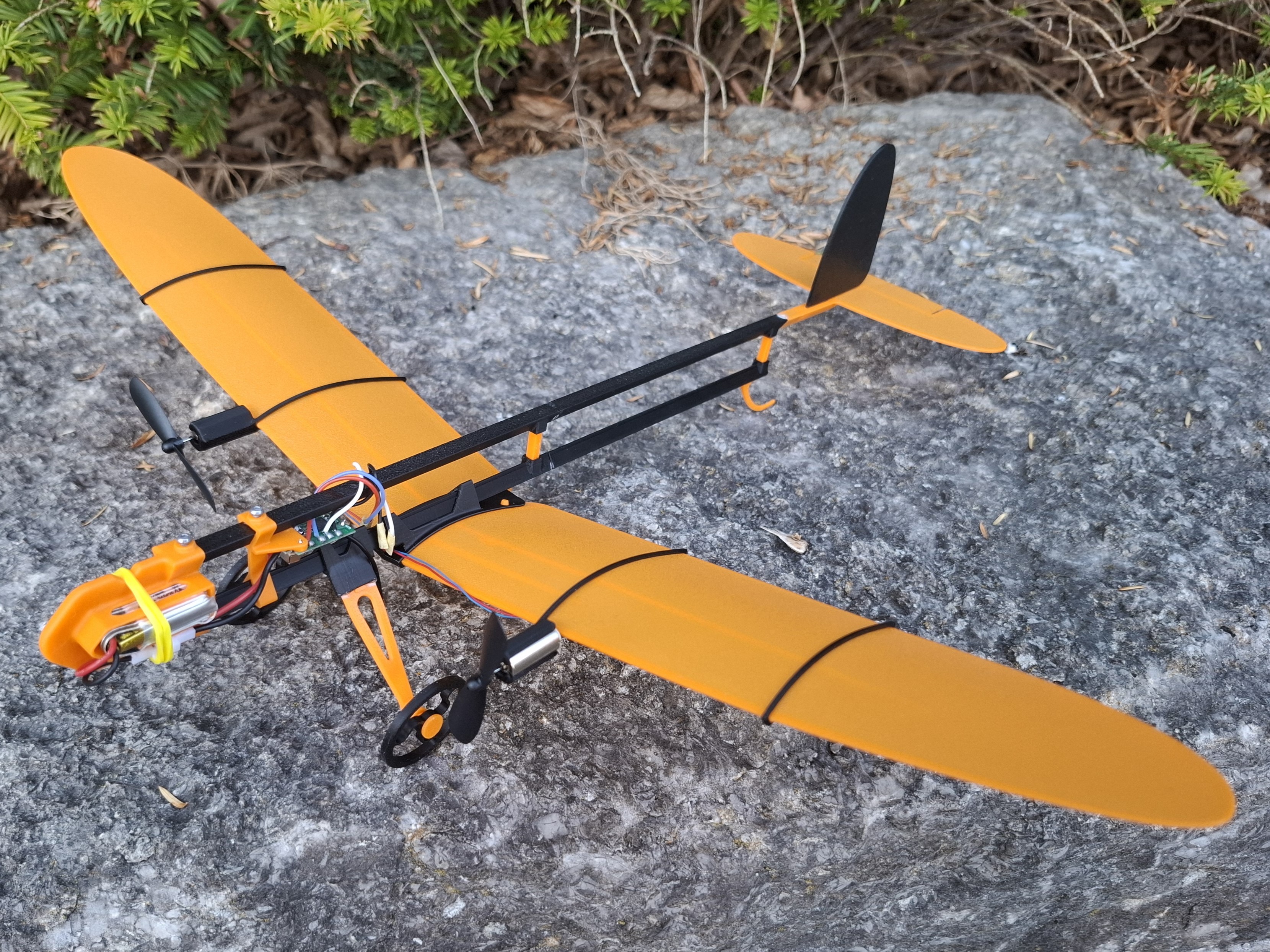
Micro- aircraft "Hummel RC"
Peso
32g
Tiempo
3h 18m
Precio
Cotiza este producto por WhatsApp
Contáctanos y te damos el precio según color y acabado
Las dimensiones dependen del diseño. Confirmamos las medidas exactas por WhatsApp.
Descripción
SIMPLE. FLYING. FUN Hummel RC is a simple and fun two-channel RC airplane designed for relaxed flights on a small field. Its modular construction is lightweight, durable and quick to print, with low material use and smooth, stable flight behavior. The adjustable wing position makes CG and pitch tuning easy. Hummel RC continues the ideas of WingStar, COMET, Wespe, SkyStar and DragonFly in a compact and practical RC model made to fly often. 1 - Model Data Wingspan: 405 mm Length: 365 mm Wing chord: 60 mm Model mass (with RC receiver, battery and motors): 43 g. 2 - Equipment RC transmitter and receiver: 2 Channel 2.4G FX803 J3 ( Aliexpress link here ) Battery: 3.7v, 220 mAh, Molex 51005 connector ( Aliexpress link here ) Motors and Props: 2x716 Coreless motors with 2 props diam 46 mm ( Aliexpress link here ) 3 - Materials, Settings, Printing Model design created and tested using Bambu PLA Basic. Use this material for best results. Do NOT use PLA Matte, especially for the wing parts. Printed parts may deform after removal from the Plate due to internal material strains after cooling. Use recommended print settings. Note: The print profile for A1 mini use slightly higher material flow coefficient (1.03 instead of 0.98). For reliable printing: Clean the printing Plate before printing. After printing, remove the Plate and let it cool for 3-4 minutes Do not remove parts while the Plate is hot. 4 - Model Assembly The model consists of 20 parts, as shown in the figure. 1 – Nose, 2 – PCB Mount, 3 – A-Beam (3pcs), 4 – B-Beam, 5 – Strut (2pcs), 6 – Sting, 7 – Tail, 8 – Fin, 9 – Central Bracket, 10 – Dual-pin, 11 – Right Wing, 12 – Left Wing , 13 – Right Big Rib, 14 – Left Big Rib, 15 – Small Rib (2pcs), 16 – Gear mount, 17 – Gear Strut (2pcs), 18 – Wheel (2pcs), 19 – Pin (2pcs), 20 – BHCS Screw M2 x 4 mm (4 pcs). Note: RC Receiver, Engines, props are not shown. The following assembly steps are shown without the electronic components installed. It is recommended to review them before installing the motors and electronics. Use cyanoacrylate glue where specifically indicated. Assemble the tail unit and fuselage as shown. Assemble the wing as shown in the figure. Use Dual-pin to fix wings. After installing and fixing the wing surfaces, install Big Ribs (13, 14) on both sides. Finally, install the Ribs (15) on both sides. Wing assembly completed. To install the wing on the fuselage, pull the fuselage beam through predefined guide points on the wing Central Bracket, as shown in the picture. A slight pushing force may be gently applied if needed. Assemble landing gear unit as shown on Figure. Install landing gear on Fuselage. To fix finally the wing and landing gear position the M2x4 screws to be installed. Do not fix wing and gear assembly finally on this step! 4.1 - Electronic Components Installation Install RC transmitter PCB on bracket (2). Finally, connect the motors to the receiver board as shown in the illustration. Before final assembly, make sure the motors rotate in opposite directions. For easier assembly and adjustment, the wires should be approximately 130 mm long. The wires are preferable to route through the rib. To install the motor in the rib, gently press it into place and slide it slightly forward until there is no gap. To prevent the motor from rotating during operation, secure it with a small piece of adhesive tape, as shown in the illustration. Install the ribs with the motors onto the wing as shown in the illustration. The motors must be positioned on the outer side of each rib. Install the wing onto the lower beam, approximately at the middle of the span. Then route the motor wires behind the lower beam and around the upper beam in a figure-eight pattern, as shown in the illustration. This routing keeps the wires secure while still allowing the wing position to be adjusted. Only after routing the wires, install the landing gear, followed by the receiver bracket (2). Install the nose part (1) and secure it with screw (20). Install the battery and hold it in place with a suitable rubber band, as shown on picture. The model assembly is now complete. 4.2 - Balancing Perform the pre-flight balancing check with the battery installed. Place the model on a Balancing Stand (model link here) using the designated balance points on the wing. The model should remain level or tip slightly nose-down. Fix finally the screws (20) of wing assembly and gear bracket. 5 - Model Flight Launch the model outdoors in calm weather or slight breeze conditions. Recommended wind speed: up to 5 km/h (≈1.4 m/s, ≈2.7 knots). Always launch the model directly into the wind. Model initially pre-balanced during assembly. Launch the model applying full throttle with a gentle horizontal push. If the model dives strongly, then: Move the wing slightly forward, OR bend the elevator slightly upward. If the model pitches up or stalls, first try reducing the flight speed. If flight speed reduction does not help, then: Move the wing slightly backward, OR bend the elevator slightly downward. Happy Flights and Smooth Landings! Boost MeBoost Me. If you like my models, hit that Boost button like it's a launch switch! 🚀
Tags
Diseñador
Arty_SC